![]() Return to HOME page
Return to HOME page
![]() Return to Station Equipment page
Return to Station Equipment page
 The
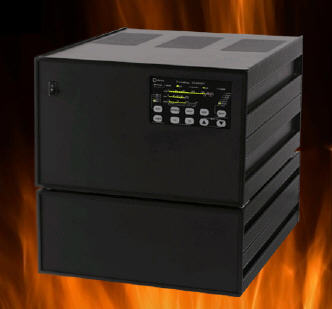
Prometheus is Amateur Radio's First Solid-State Legal-Limit+ 160-10m
HF Amplifier. With no tuning and no warm up time delay, the
Prometheus provides reliable power instantly so that rare DX station
does not get away. This is a rugged, commercial quality amplifier
designed to run cool under 1500W continuous SSB, CW or RTTY, with
special ferrite transformers and combiners designed for full power
operation even on 160 meters. The
Prometheus is Amateur Radio's First Solid-State Legal-Limit+ 160-10m
HF Amplifier. With no tuning and no warm up time delay, the
Prometheus provides reliable power instantly so that rare DX station
does not get away. This is a rugged, commercial quality amplifier
designed to run cool under 1500W continuous SSB, CW or RTTY, with
special ferrite transformers and combiners designed for full power
operation even on 160 meters. There is a user group I started to serve as forum for sharing information, ideas and experiences. The user group is located at: https://groups.io/g/PrometheusDX2400 Information about the amplifier is available at: http://www.dishtronix.com/prometheus.html |
I have been looking at this amplifier for about 3 years at the Dayton Hamfest and decided to order one this year (2009) after the show. I'll chronicle my experience here with pictures and notes.
"This amplifier is really a beautiful piece of workmanship"
Ordered on 20-May-2009
Received Serial Number 0014 on 22-Jul-2009
Installation and preliminary testing complete on August 7, 2009
Quick links to the sections below -- click on the BLUE hyper-link
Photos - preparation, and setup
FLEX 6700 cable adapter box and serial frequency data
Power Supply Cables - shorter length for stacking
Fan Filters - noise reduction option
Power Supply - Assembly of the power supply is straight forward. The transformer is heavy (71 lbs) but not really a problem to manage. Same for the choke (44 lbs). Once fully assembled you will need help moving it around since the total weight is 145 lbs. The transformer has a buck/boost tap if you need to make any adjustments due to over/under primary voltage at your QTH. Mine was right on with an output of 74.5 VDC for the RF deck.
Interfacing - The next step is to decide on the method of connectivity to use between your station equipment and the DX2400. The amp supports 2 radios for S02R but in my case, I'll just be using one (Yaesu FTDX9000). Since it's a modern radio, I'm using the full loop FSK interfacing method. The amp also supports PTT and other methods that can be used with older radios.
Cables - Dishtronix will provide all of the cables you need but for 2 reasons I decided to build an interface breakout box. The first reason is I use a SteppIR 4el yagi and the N8LP steppIR tuning relay to inhibit the amp when the antenna elements are moving. The second reason is this installation is the first DX2400 connected to a FTDX9000 and the interface box will make it very easy to "re-wire" the cable if necessary. Pictures of the interconnection box are below.
Exciter options - I elected to turn on the 3db attenuator for the driver input. The DX2400 has this as an option and since the FTDX9000 is a 200 watt rig, it provides a little more protection against over driving the amp. Combined with the ALC from the amp and the extensive fault protection this seems like a good choice for me. By the way, the attenuators can be selected (or not) for each of the 2 transceiver inputs.
ALC - The support for the ALC output allows you to tailor it to the needs of your radio. In my case, the FTDX9000 likes it to be between 0 and -4 volts. Driving the amp with about 120 watts (60 watts without the 3 db attenuator) produces a solid 1,500 watts of output. The ALC keeps it there as the driver power is increased.
Some Other options - The fans can be configured via software to run continuously or only come on as needed. In my case, (a casual DXer) I've set the fans to come on as needed. There is one fan in the power supply and four fans in the RF deck. If you are a serious contester you may want them to run continuously. The amplifier can be configured to start up when you turn on the rig and be in operate or bypass mode (or what ever mode you last used). (It looks like Mike has covered all the bases and lets you decide what works best for you. )
What they are not -- My testing feedback will not be "Sherwood" type test results. The comments and feedback will just be the impressions of a user. I'm a "CW only" OP so there won't be any feedback on SSB operation. I'm also a casual DXer (40+ years) and not a contester. I tend to use my amp occasionally (when I'm trying to get a needed one). My previous amplifier was an Alpha 87A so my comparisons will be relative to it. I had the 87A for about 10 years and it worked well. I like trying new equipment and really wanted a legal limit, "instant on" solid state amp. The longest 3 minutes in a DXer's life is while you are waiting for the tubes to warm up. Especially if you just heard a new one come on and the pileup hasn't started yet!
12-Aug-2009
So far, I've been mostly getting familiar with the amp, re-reading the manual, and checking it out with my various antennas. I loaded a firmware update (see notes below). I've let the amp run for about 8 hours to see if there would be any issues. No problems, when I need it, it just works. I've made a few contacts. So far it performs great, the signal reports are 599+ (as you would expect).
15-Aug-2009
The four fans in the RF deck cycle as needed when using the amp. The one fan in the power supply didn't cycle until I made my bleeder thermostat modification. (see notes below). The power supply fan was working as designed but after the modification it cycles periodically now. I've been making more Q's and on testing on more bands. The amp is working great and loads my various antennas well with no tuning or adjustments needed of any kind. I've asked Mike to make a shorter set of power supply cables, see section of shorter cables below
25-Aug-2009
No problems to report, the amp is working great. I did decide to add some fan filters. See section below.
12-sep-2009
The new, shorter cables are installed, and everything is working fine. Unless something new comes up, the next report will probably be after the remote PC software is available. In the mean time "gd dx es cu in the pileups."
There are always opportunities to improve, and ideas to make things even better. In the past, it was not so easy to do this but with software defined radios and a good hardware platform, the possibilities are endless. I'll add my suggestions here, although I know some of them are already in the works.
Manual - the manual is very good but I find the some of the diagrams a little too small and hard to read. Another option is to provide a soft copy of the manual in .pdf format so it can be zoomed in on screen. I haven't asked Mike for a soft copy yet, so this may already be available.
Remote PC program - Steve / K5FR is the author of DDUtil and a DX2400 owner. He is working with Mike to provide a remote interface. I'm really looking forward to this enhancement. If you aren't familiar with DDUtil, it is an excellent rig and equipment control program. Take a look at http://k5fr.com/ddutilwiki/index.php?title=Setup#Amps_Tab for the section on amplifier control.
Power supply thermostat -- See my fan mod. Mike has agreed to add this to future amplifiers. That was fast and easy....and a level of responsiveness you don't often see these days.
There must be more....but so far I haven't found anything else. This is really a beautifully engineered amp but I'll keep looking. If anyone else has suggestions, I'll be happy to log them here.
Like any modern amplifier, software runs the show. If the amplifier software ever needs to be updated, it's a very simple procedure.
Here is what you need to before you start:
1) New firmware. This is all contained in the single executable file provided by Dishtronix.
2) Your configuration settings (if you didn't write them down in the manual, now is the time to do it)
3) The DX2400 programming cable
4) A PC or laptop with a serial port. If you don't have a serial port, you can use a USB adapter. The port should be set to 9600 Baud, no handshaking.
Here are the basic steps to load the new firmware:
1) Connect the programming cable from the DATA A input on the amp to a serial port on your PC.
2) Put the amplifier in Firmware update mode (BAND + Power ON )
3) Turn on you rig or otherwise insure you have the optically isolated interface powered up. (+12V on pin 8 on the 13 pin Din)
4) Load the Update Program on you PC. Pick the appropriate COM port and click the "Load Firmware" button.
5) The program will "erase the flash" and then display a progress bar as it is loading the new software. It only takes about a minute.
6) When it's finished, power off the rig, amp, and remove the programming cable.
7) Check / reset ALL of the menu
options.
That's all there is to it!
The power supply has a cooling fan mounted at the rear of the supply. It can be set to run continuously (for contesting, FM, or other continuous modes) or to come on when the temperature of the rectifiers reaches 120 degrees F. The rectifiers are also mounted at the rear of the power supply. The power supply is loafing for CW and SSB and the rectifiers never get hot enough to activate the fan. However the 50 ohm, 100W bleeder resister at the front of the power supply will get quite warm and consequently the front panel also gets hot. While this is not really a problem per Dishtronix, I decided to add another thermostat near the bleeder resistor. The part I selected is a Stancor STC-120 which costs less than $5 from www.mouser.com. This thermostat will close at 120 degrees and open at 90 degrees. I used a digital thermometer with a remote sensor applied to the front panel for the tests. I checked with Mike at Dishtronix and he approved this modification since it does not disable the existing rectifier temperature protection.
WARNING -- be sure to disconnect the 240V mains before working on the power supply!
Test results
Before - the front panel would register 125 degrees after 1 hour of operation. After 2 hours the temperature reached 129 degrees. This equates to an internal temperature of about 152 degrees. (Based on my testing there is about a 23 degree differential between my thermometer reading and the internal temperature when the supply is operational.)
After - the fan cycles on when the front panel reaches about 97 degrees after about 10 minutes. Your time may vary depending on the ambient temperature and exact location of the thermostat. Note, the temperature required to trip the thermostat is 120 degrees, so the differential between my test thermometer and the internal temperature is about 23 degrees. In my test, with the fan running, and while using the amp, the front panel temperature stabilized at 90 degrees which equates to an internal temperature of about 113 degrees. If the amp is not being used continuously and the ambient room temperature is low, the fan will cycle every 15 minutes or so. The fan runs until the internal temperature drops to about 90 degrees before cycling off. If you put the amplifier in HARD BYPASS the fan will also shut off.
Additional considerations - If you would prefer the fan to come on later, you can substitute a STC-140 thermostat (closes at 140 opens at 110) and/or move the thermostat further from the bleeder resistor. There appears to be about a 30 degree difference between the front and rear of the supply when the fan is not running.
Here is a picture of the power supply before the modification with a digital thermometer and sensor temporarily stuck to the front.
The modification consists of adding a Stancor Disc Thermostat (STC-120) in parallel with one of the rectifier thermostats. The STC-120 thermostat closes at 120 degrees F and resets at 90 degrees F.
WARNING -- be sure to disconnect the 240V mains before working on the power supply!
WARNING -- be sure to disconnect the 240V mains before working on the power supply!
Looking toward the rear of the amplifier. The dark GREY leads originally went directly to the thermostat on the rectifier bank on the left. Connect the new bleeder thermostat in parallel with this rectifier thermostat (not the one with the WHITE wires on the right).
WARNING -- be sure to disconnect the 240V mains before working on the power supply!
Closeup showing where the GREY leads are cut and the spliced back along with the RED twisted pair leading up to the new thermostat.
WARNING -- be sure to disconnect the 240V mains before working on the power supply!
Although it looks closer, the thermostat is actually several inches above the resistor and cable tied to the capacitor leads. Also note the push on connectors are covered with clear push on insulation.
Photos --
Preparations, unpacking and setting up the DX2400
Preparations -- The amp will sit next to the shack PC on a sturdy mahogany lateral file.
Packages arrived on 22-Jul-2009. The outer box for the RD Deck was slightly damaged but the inner box was fine. From top to bottom, left to right, the weights below are after removing items from the packaging.
Top - Power Supply ( 30 lbs without choke and transformer, 145 lbs with them installed)
Middle - RF Deck ( 60 lbs)
Bottom Left - Choke (44 lbs)
Bottom Right - Transformer (71 lbs)
Total weight 205 lbs!
Power supply, cables hardware and manuals shipped together. The custom packaging did a good job.
Heavy duty (and heavy) choke (44 lbs) and transformer (71 lbs).
Plug on right is what comes from the factory. Plug on left is the one I use.
Added some felt pads to the power supply feet to prevent scratching the table where it will sit.
The RF deck resting on the foam innner packaging
Closeoup of the control panel.....
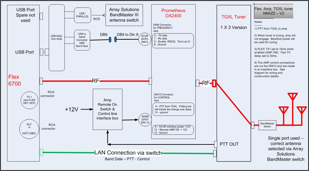
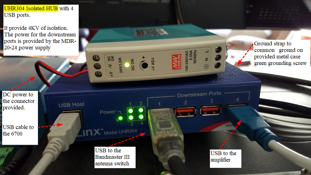
Setup to use a FLEX 6700 SDR radio, Alpha 4040 tuner (future) with the DX2400. To support the various connections and provide a "remote power on" switch for the DX2400, I built an adapter box. Here are some diagrams and pictures. Visio diagrams and additional details available on request.
Station equipment to interface with the 6700
Wiring diagram for the interface between the FLEX 6700, Flex TGXLtuner, Array Solutions Bandmaster III antenna switch and the DX2400 amplifier. USB interface from 6700 starting with V1.10.8
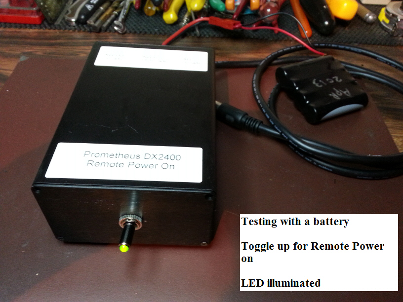
Interface box for the various connecttion to the BAND DATA DIN 13 connection. Also houses the "remote On" switch
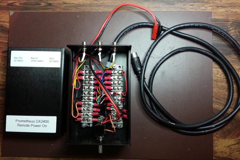
The Black cable goes to the 13 pin DIN on the DX2400. The barrier strips provide an easy means to configure signals for the RCA connectors. The 13 pin DIN and cable are available from Digikey (soldering the 13 pin can be difficult so the premade cable is nice. . The RCA connectors provide ALC, KEY IN, and KEY OUT.
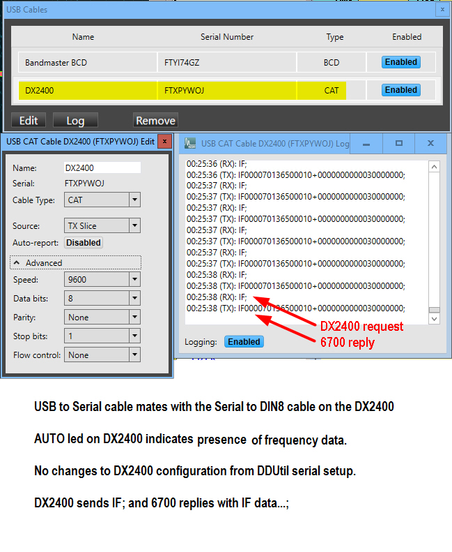
Frequency data from the Flex 6700 via the USB on the radio ( SSDR V1.10 and later)
***** Cable from DX2400 ****
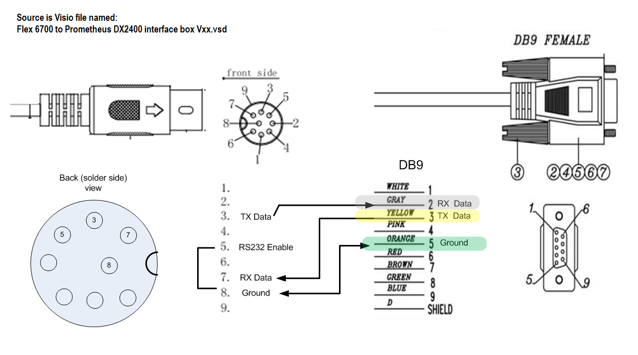
***** Mates with this USB cable from the 6700 USB port on the radio *****
***** 6700 USB configuration in the SSDR USB setup screen *****
***** Example of the data flow *****
Rear view of Power Supply and RF Deck
Cabled up and ready to go. See section below on the shorter cable option
Installation and preliminary testing complete on August 7, 2009.
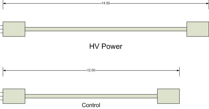
Power Supply and RF Deck interconnect cables - shorter cables.
There are two power cables and a control cable between the power supply and the RF deck. The default length of the cables is 3 feet. This allows you to put the power supply and RF deck side by side or stack them. Dishtronix will build custom length cables for you if desired. The 3 foot cables work fine and if you use them in the stacked configuration I'd suggest using a small bungee cord for strain relief. Since I'm only going to use my amplifier in the stacked configuration I asked Mike to build a new set of shorter cables. Pictures below of the current 3 foot cables, a diagram with requested new lengths, and I'll add a picture of the new ones when I get them installed.
Three foot cables, note strain relief.
New shorter cables installed
The Prometheus has a total of 5 fans (1 on the power supply and 4 on the RF deck). I have them all set to run only when needed but when all 5 are running they are noticeable. They are not the loudest I've heard but compared to my Alpha 87A they are louder. I'm running my amp regularly now but eventually will go back to my usual routine of only using it when I need to. Generally that's chasing a rare one and more often than not I'm using headphones so the fan noise is not really a problem. Dishtronix offers the optional fan filters. They help keep dust out if you are running in a dusty environment and also reduce fan noise. I didn't order them initially but decided to get a set to see the difference. Mouser carries the same fan and filter kits, so ordered from them. I decided to install both the wire mesh and foam kits for maximum noise reduction. I only installed the filters on the external 3 fans, the RF deck also has 2 internal fans. Here is some info and pix on the fan and filter kits. Note, adding filters will reduce the air flow somewhat. In my testing I could not notice any difference in the cycling so it does not seem to be significant. The noise level is reduced and the cost is only about $8 per fan.

I installed both the mesh and foam filters for maximum noise reduction but you don't really need both. After removing the stock wire guard, just bolt the plastic "guard" piece and "wire mesh guard" to the fan with longer 6-32 flat head screws. The foam and retainer snap in place.
More to come....