![]() Return to NN4ZZ HOME page
Updated on:
Wednesday, March 15, 2017
Return to NN4ZZ HOME page
Updated on:
Wednesday, March 15, 2017
![]() Go to the TiltPlate page
Go to the TiltPlate page


Thanks to Dennis
Motschenbacher, Miki Maruya, Scott Dolliver, Mr Hiroshi Ogi
and the engineering team in Japan for the great work they have done bringing
this program to us!
This web page started out as a place to share my experiences with the PEP
program. It has evolved to also include a few tips about the 9000 and how
to use some of the features.
Quick Links to the sections below.
If I can answer any questions
or if you have any comments about this page, please email me or post them on the
FTDX9000 Yahoo group.
![]() Click to
mail
--->
al@nn4zz.com
Click to
mail
--->
al@nn4zz.com
July 2008
My evaluation was on July 27, 2008. I was one of several individuals that had the opportunity to contribute to the effort. Lou / N2TU was field testing at the same time and I've included some of his feedback on my web page. The final delivered PEP product may not be exactly as I observed so please refer to any official descriptions, etc that are provided by Yaesu.
First, here is what my test was and what it was not.
► It was a chance to try out the new PEP upgrades in operation for a few hours in July of 2008
► It was NOT a "Sherwood" type performance review. (I don't have the tools or knowledge to evaluate equipment to that degree).
► It was a chance to make a few contacts and see how the rig functions.
► It was a chance to see if some of the "bugs" we have reported were fixed.
► It was a chance to see if some of the enhancements we requested are included and to see what else the engineers have come up with.
► I was able to do A/B comparisons between the PEP rig and my 9000C rig (Note, my rig was NOT upgraded as part of the test).
► It was focused on CW operation (I'm a CW only OP).
► It was not a test of all modes (Lou and other testers looked at SSB, the digital modes, etc).
► I did not get a chance to evaluate some features such as the AGC. It's my understanding that there have been some additional improvements made since I saw the rig but I didn't have any issue with the AGC as it was.
►
Here is some
background to help you evaluate my observations. I've had my FTDX9000C
rig since July 2005. I don't have any financial interest in
Yaesu but
have owned a number of Yaesu rigs over my 40+ years in radio. I've
been active in the FTDX9000
forum since it started and serve as one of the moderators.
► The Noise Reduction is greatly improved in my A/B tests. This is the control that selects one of the DSP algorithms to reduce background noise. This is not to be confused with the NB (Noise Blanker) button which I don't use. The Noise Blanker is intended to reduce impulse type noise (ignition, electric fences, etc). Click for more info.
► The sporadic "keyer hiccup" is fixed.
► The Bandscope speed is much faster, works great.
► NEW Bandscope frequency lines were added. This was an enhancement I requested and think it makes it much easier to see where the signal are. See pix below.
► The firmware version can viewed without having to do an upgrade to see the current version. See Pix and notes below.
► I didn't test the CAT port performance but Lou / N2TU reports the CAT delays are eliminated. The processor is very fast.
► NEW auto-peaking feature for the Contour control. Press and hold the CONT button and it auto peaks a signal. Click for more information
► NEW CW speed display. When you adjust the speed control, it is momentarily displayed on the screen (see pix below) This is great for CW ops. We can QRS and then come back to our preferred speed quickly and easily.
► I checked as many of the bugs from our database (posted in the forum) as time permitted. I didn't see any that were missed, however it was not a thorough examination.
► I made a few contacts and the rig performed flawlessly.
►
My overall impression
from the field test was
WOW! This is going to make a very
good rig really GREAT!
November 2008
► My FTDX9000C was shipped to Cyprus for PEP on November 10, 2008 and received back in my QTH on 24-Nov-2008. Total time away from the QTH was 14 days.
► The following parts were replaced in my rig. (may not be the same for all upgrades)
►
Cntl-Unit
►
TX- Unit
►
DSP-Unit
►
SCP-1 Unit
►
RX-1 Unit
 This label is on the rear of rig showing the PEP upgrade was
performed
This label is on the rear of rig showing the PEP upgrade was
performed
► My first impression is the receiver seems noticeably better (maybe part of this is a result of the alignment that is included in the upgrade). Signals are clear, noise levels are lower, the myriad of options to pull out weak signals are working great.
► Bandscope - After using the bandscope on my external 19 inch monitor for a while, it is really working great. There is a big improvement in performance and usability. The display refresh is fast. The new pointer lines and frequency markers make it much easier to read. There are pictures below of both the D model with the internal TFT used in the field test and my C model with the external screen.
► My Screen - With PEP you can skip unused screens (MYSCRN Menu item) on the TFT or external monitors. No more need to page past the logging program or rotor control screens... you can customize the TFT to your preference. I leave my display set to the bandscope so this is not as important to me but I can see where it could a big deal for some. I think this is one of the enhancements Lou / N2TU requested.
► Digital Noise Reduction - The DNR works much better as noted in the field test observations. See enhancement request below.
► Noise Blanker - I haven't had the need to use this feature but Lou / N2TU reports a **massive** improvement from my non- PEP 9000D. (it was miserable!) As you probably already know...the NB in the FT9000 (and 2000, I think) has to be slowly applied allowing the NB algorithm to catch up. Once it does (within a second), it is very effective.
► Software Updates - After receiving the rig, I needed to load an update to correct a minor problem. See the pix below showing that process and the current software version information.
► CW Speed Display - The new CW speed display feature works great and another very nice new "usability" enhancement for the CW OPs.
► Contour control - The contour operation has been improved and enhanced. Click here for a summary of the changes and details on the new AutoPeaking mode.
► The IF bandwidth (for CW) works better now at 100 and even 50 after the PEP upgrade. Previously at settings of 100 and especially lower, there was excessive ringing. There is still ringing at 25. I can't say whether this improvement is related to the PEP upgrade or the alignment.
► CW Slope and CW Shape menu settings - I experimented with the CW slope and CW shape settings and can't say whether they are any different than before. The effect of any changes from the default is minimal.
► Cat Control - I only use the CAT output to control my SteppIR 4el yagi but it is working fine. Lou / N2TU has done a number of tests with the software interfacing via the Cat port and can provide more information on this. He noticed that the CS light (in switch #37) now flashes when the rig is being polled by the CAT interface. Click here for more information on Lou's findings regarding the rig control software.
► CW Pitch frequency - This is new, when you adjust the CW Pitch frequency, it is displayed on the bottom of the VFO A screen.
► Notch Filter frequency - This is new, when you adjust the Notch Filter, the notched frequency is displayed on the bottom of the VFO A screen.
► VFO-B Toggle bug - This was a problem only for the Contest models. It was reported in 2006 and has been fixed, details below.
► QSK relay clicking - Disabling the TX Ground (menu item #170) now prevents the TX GND relay (RL2501) from clicking. There will still be a faint clicking heard from another relay (possibly RL2502) but the sound is much less. John / W9RPM & Jim / KJ0M both asked us to check this from them. In the pre-PEP rigs the TX GND relay activated regardless of the setting. Lou / N2TU and I both verified the relay does not activate on the PEP upgraded rigs when menu item #170 is set to DISABLE.
► There are always opportunities to improve, and ideas to make things even better. In the past, it was not so easy to do this but with software defined radios and a good hardware platform, the possibilities are endless. As users, we have a place to collect our comments, and enhancement requests in the FTDX9000 forum. See the new PEP Log database in the forum. There are a few more notes about the database posted below. Owners are encouraged to post to this central repository for feedback.
► Digital Noise Reduction - I entered a record into the PEP Log database suggesting a further enhancement that was first reported by K2XX in 2007. As the user moves the DNR knob, provide a visual indicator to show which of the 16 noise reduction algorithms is active/selected. For example display the number 1-16 for a few seconds. Since the knob does not have mechanical detents, this would serve as a virtual detent. Further, since each algorithm take a few seconds to settle, provide a visual indicator showing that the current algorithm is settling. For example blink the number while settling. UPDATE - added in V509 along with the ability to control when the information is displayed via a new menu item #22
► John / W9RPM reports that the documentation in the latest version of the manual has not been updated with instructions for entering a new city name. There is a process to do this he got from Chip several years ago but it needs to be documented. UPDATE - 3-Dec-2008, Miki reports the manual has been updated and posted to the Yaesu web page.
► Contour - menu item 83. The nulling values (down to -40) work great. The peaking values (up to +20) do not provide much peaking. Regardless of the positive amount the peaking is only slightly above normal. In the pre-PEP rigs, the peaking was very noticeable which could result in distortion at the higher values. While this is no longer a problem, a middle ground with an additional amount of peaking is needed. I entered a record in the PEP log for this enhancement request. UPDATE - 1-Feb-2009 Peaking added back in V510 11.49
► The complete database of enhancement requests is maintained on the FTDX9000 forum. The requests listed above were entered during the first few weeks evaluating the PEP upgrades. The Yaesu team has been extremely responsive in addressing these!
July 27 PEP field test at NN4ZZ in Loganville, GA
► Left to right The 9000, Mr Ogi, Al/NN4ZZ, and Miki
► My station and 9000C in the background
Here is a picture of Miki, Lou / N2TU, and Mr Ogi field testing at Lou's QTH on 29-July-2008
You can contact Lou at N2TU@arrl.net
Closeup of screen - D model test rig
► CW speed (25 wpm) displayed momentarily whenever you adjust the speed
► Bandscope lines drop to base (makes it much easier to see where you are)
Below - Display on my 9000 Contest model rig with the DMU option and an external 17 inch monitor
Closeup showing the line for VFO A and the frequency markers.
A snack after a morning of testing, July 27 2008
► Left to right Al, Mr Ogi, Miki, and Lida (my XYL)
Custom Shipping Case from SouthPak
► Plasti-Cad case weighs about 30 pounds
► Original Yaesu carton is 27 x 27 x 12 and weighs about 10 pounds. It is encased in 2 inches of foam.
► Total shipping weight with radio is about 107 lbs
►
Cost for the case is $527.58. For more information on the
custom plasti-clad case for the 9000, contact Norry at 800 541-9834
Dexter our UPS guy loading his truck for
UPS 3 DAY SELECT
pickup date 10-Nov-2008
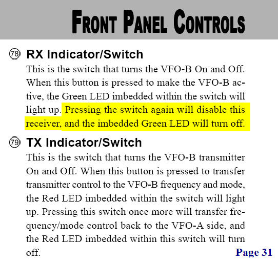
There was a bug reported back in 2006 regarding the RX operation of the VFO-B switch #78. See snapshot below. It only affected the CONTEST model rig. This switch did not toggle as indicated in the manual. It has been fixed to work as documented.
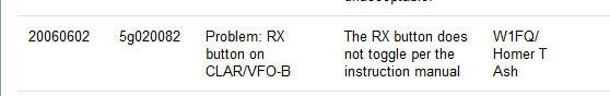
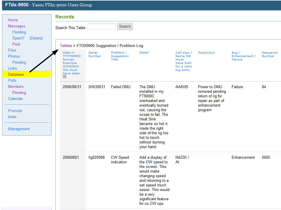
The original log file was created in 2006 and is located in the database section of the forum. This was one source of feedback to the engineering team for the PEP. Here is a partial snapshot and a guide to help you locate the file.
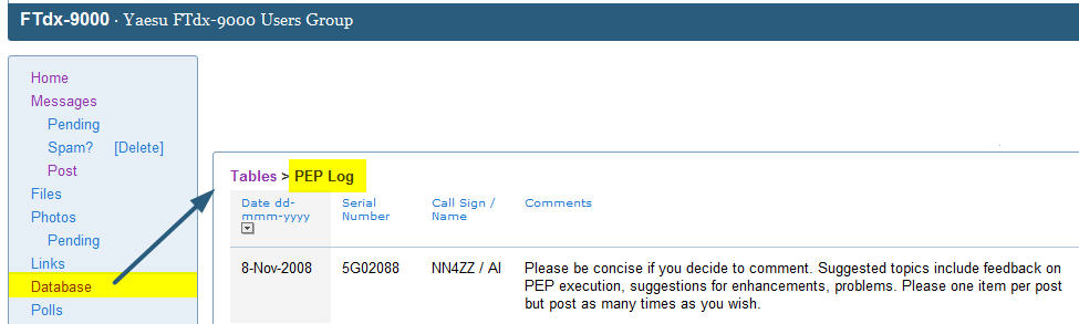
The new PEP log was created in November of 2008 and is located in the database section of the forum
Date - please use the yyyy-mm-dd format (to force proper
record sorting)
Serial number - of your rig
Call / Name - call is required
Comments - if you decide to provide some feedback, please be concise. This is
not meant to replace any comments you would like to post on the forum (and be as verbose as you would
like). The database is meant to be as place to collect feedback in a single
location. You are encouraged to comment on:
►
Feedback on the PEP program execution
►
Impressions of the enhancements
►
Suggestion for future enhancements
►
Problems you encountered
Use of the database is completely optional.
How to display your current version
Start with the rig off. Press and hold these 3 buttons (50, ENT, GEN) and then press the power button on the front to turn on the rig. The current version is displayed on the 9000 display above the main tuning dial on startup. You can use this sequence at any time to see your current versions.
Here is how to interpret the numbers. For example, the version on my CONTEST rig as of 15-Feb-2009 was displayed 11.505.11 followed by 418 on the second row. Here is what the numbers mean.
► 11.50 is the DSP software version
► 5.11 is the CPU software version
► 418 is the DMU software version number
Main Processing Software
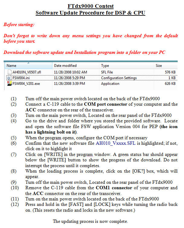
A new version of the software update program (FSW004) is needed to install updates after PEP. Normally you would use COM1 but as you can see below, I used COM5 with a USB adapter cable.
Here are the typical instructions for loading main CPU software....always refer to the specific instructions posted on the Yaesu web page with each software update.
DSP Software
The DSP software is updated via the CAT port now using a new program and DB9 female / female cable
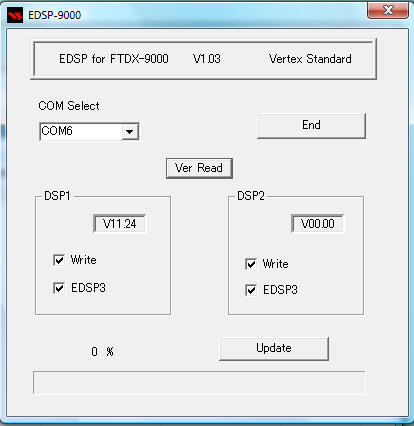
One step in the process is to put the 9000 in the mode to receive the DSP software. This is done with a power up key sequence. Prior to the main software version V515, a 3 button press was required. After V515 only 2 buttons are required. Both the old and new sequences are listed below.
Prior to V515 -- Here are the correct three buttons to hold for the contest model and MP models.
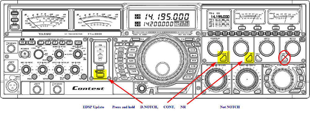
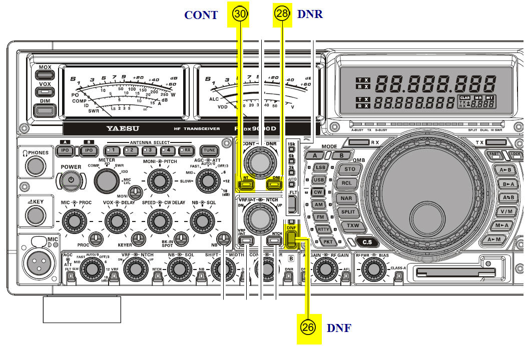
Here are the buttons to push for the D model
What cables do I need to perform the Update?
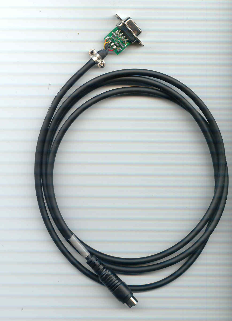
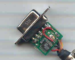
CT-119 programming cable - this cable is used for the main CPU software updates and connects to the ACC port on the 9000. Effective with the V511 release, there is now an option to use the COM port on the 9000 for all software updates. See section further down for details.
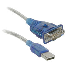 I
use a "Port Authority" brand USB Serial DB9 Adapter Cable (not
required if you have a serial port available on your PC).
I
use a "Port Authority" brand USB Serial DB9 Adapter Cable (not
required if you have a serial port available on your PC).
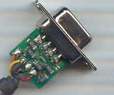
DB9 Female to DB9 Female for DSP updates
You will need a DB9 Female to DB9 Female straight thru cable (NOT a NULL modem cable) for the DSP updates. This cable connects to the CAT port on the 9000. If you are using rig control software, you already have this cable in place.
New with V511 - You can use the 9000 COM port for all software updates
The notes below were originally posted on the 9000 forum by Lou/N2TU on Feb 13, 2009
As many of you all ready know, the FT2000 series
radios can be upgraded without the need for the CT119 cable. The software
information is fed to the FT2000 via the CAT port. The FT2000 needs to have a
micro-switch moved to the 'On" position or a 'modified' plug inserted in the 'Prog"
port. Now effective with V511, this procedure can be used for the FT9000
series as well.
The FT2000 procedure is posted on this website, along with the information on
how to build the plug. One wire from pin 4 to the shell of the plug...rather
simple!
http://www.wlog2000.com/ft2000
Or you can order a part number P0091526 from Yaesu
(recommended). However, as of Feb 1, the part is this is not
currently available from Yaesu. Mouser has them in stock and here is
the information.
Mouser Part #: 806-KMDAX-8P
Manufacturer Part #: KMDAX-8P
Manufacturer: Kycon
Description: Mini-DIN Connectors 8P ASSEMBLY PLUG CABLE MOUNT
$2.01 plus shipping.
Some ingenious hams have also put an on/ off switch
on the plug and leave it in the rig. That way, you do not need to fish around
behind the rig when you upgrade.
The exact procedure on how to use the 8 pin mini-DIN
PGM-SW was contained in the last Upgrade Instructions on the Yaesu website,
however, there was an error on page 3. Step 4 should read "Insert the 8pin
mini-DIN Pgm-SW connector into the FT9000 ACC port." As always, refer to the
latest instructions as posted on the Yaesu website.
So there you have it! Yaesu has made upgrading the FT9000 as simple as the
FT2000 series. No more need to assign a com port to the CT119 or attaching the
CT-119 to the rig. Simply attach the plug as directed in the instructions and
update the CPU via the CAT port.
See note below about COM port speed in updated installation instructions for V511 / 11.50

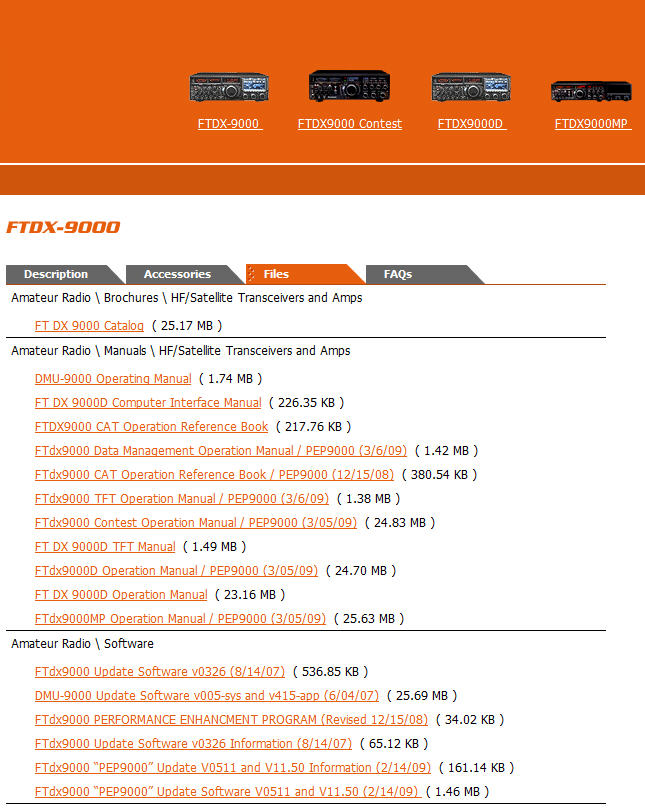
Go to the Yaesu web page and look in the FILEs tab for your software updates and manual revisions. Here are some short URLs you can click on or paste in your browser to get there....
http://tinyurl.com/dxuv9r All models
http://tinyurl.com/c52pr7 CONTEST model
http://tinyurl.com/6n6k55 D model
http://tinyurl.com/chmu4p
MP model
The page will look something like
this.....depending on your model
Are you looking for older versions of the software or manuals?
Join the Yaesu "Owners Corner" and you will have access to all of the older versions. Click here to signup and then just add your products. http://www.yaesu.com/indexVS.cfm

Ver. 506 & 11.24 (EDSP), 418 (DMU) The original PEP software, November 1 2008
AGC… attack time fine-tuned
DNR… superior SSB mode noise reduction
DNF…greater reduction of beat tones
Contour - new autopeaking feature added
Digital Filter... increased Sharp/Soft differentiation
SSB speech processor audio augmented
Faster CAT COMMAND communication
CW side tone clarity
Activate RTTY monitor while transmitting
Reduced Ringing during CW super narrow receive band width settings
Ver. 0507 28-Nov-2008
Corrects a CAT
Added CAT commands: FT0, FT1:
simplex/split (toggle)
FT2: SIMPLEX
FT3:
Ver. 0509 13-Dec-2008
Add MENU #022 LEVEL Indicator for PITCH・SPEED・CONTOUR・NOTCH・DNR
CW DELAY・VOX
DELAY (Press the [ENT] key to set the command to “ON” or “OFF”)
Ver. 11.29 (EDSP) 3-Jan-2009
DELAY characteristic of AGC close to analog AGC
Ver. 11.39 (EDSP) 12-Jan-2009
Improved RX-TX switching noise
NOTE from Yaesu with this update : If you have EDSP V11.29 in your FTdx9000, do not continue to use it. Please install the new EDSP V11.39. It has improved the RX-TX switching noise, and an important engineering change, no operational changes are included. On inquiry about the change, "An engineering issue is always important. No additional information is released."
Ver. 0510 1-Feb-2009
Added values are now indicated on the VFD
display for MIC, PROC and RF PWR. (Press the [ENT] key to set the command to
“Enable” or “Disable” MENU #022 LEVEL INDICATOR).
Ver. 11.45 (EDSP) 1-Feb-2009
The characteristic of the CONT LEVEL is changed.
Ver. 0511 15-Feb-2009
Add MENU #87 and #90 (Available Values: APF/CONTOUR/APF&CONTOUR).
Press the [CONT] switch for 2 seconds to activate the APF (Audio Peak Filter) which provides a very narrow audio filter in CW mode.
Ver. 11.50 (EDSP) 15-Feb-2009
Corrects a low audio problem found in Ver. 11.45.
Corrects the CW-DET indication problem found in Ver. 11.45.
Ver. 0512 31-Mar-2009
When AFP is active the control
LED can be selected to blink or steady. The timing of the AFP blinking indicator
can be selected MENU # 023 (STEADY ON or BLINKING 1 ~ 60 sec).
The CW-DET indication is
improved.
Corrects the CAT MG command.
Ver. 0513 2-Apr-2009
Correct the PC keying.
Change the adjustment characteristic of the TX power control. (After installing V0513, you should verify your TX power level settings)
The level indication requires a quicker knob rotation to activate, before making fine adjustments. A slow knob rotation may not activate the display
Ver. 0514 9-May-2009
- Improve response time of the values indicated on the VFD display. (CW Speed display, DNR, etc now displays more rapidly....Al's note)
- Correct the PC-keying.
- Correct the INDICATOR VOX-DELAY.
- Correct the AM reception GAIN.
- Correct the MEMORY KEYER output.
Ver. 11.53 (EDSP) 9-May-2009
- The DNR algorithm is not reset between TX/RX, to eliminate the increased receive noise after a transmission.
- Increase the response of the compression level meter in conjunction with the PROC knob. (Max up to 12dB).
Ver. 0515 23-Jul-2009
- The REC (Record Function) setting will be recalled when the power is turned on if REC was turned on before power was turned off
- The CAT MW command is corrected
- In the QMB-MT mode, when the VFO frequency is moved, the memory channel indication is cleared to 0.000.
-The DSP firmware write mode may be accessed by pressing [CONT] + [DNR] while pressing Power On.
- Holding of the [down]F6 or [up]F7 keys will permit scrolling through the DMU [MCH-LIST], when the DMU-9000 is installed.
- The FH-2 [down][up] keys are made the same function as the MIC-UP/DN keys.
- In 30-500 kHz BAND operation, the IPO is always ON. (LED does not light)
Ver. 0518 30-Nov-2009 (Al's note....there is no V516 and V517)
• The CW MEMORY KEYER MESSAGE TEXT save is corrected.
•
The FH-2 [<-][->] keys are made to increment the frequency at 100kHz up or down.
•
CW carrier is corrected to change LSB
⇔
USB when the indication is changed on VFO B.
• Correct the CW Auto Mode.
• DMU Band Scope Display Signal Peak Frequency is centered.
Ver. 11.54 (EDSP) 5-APR-2010
The current release is EDSP V11.54 for current production units for the FTdx9000, FT2000 and FT950. Between 11.53 and 11.54 there was a slight correction of the FM transmit frequency offset. We have released this on the website however there is really no necessity to install this version as all other performance is not affected.
CHANGE: Corrected FM TX for a slight frequency offset.
Ver. 0519 24-Apr-2010
KEYER: The extraneous “dot” memory is eliminated during rapid keying when the dash output starts.
CAT: Correct the 1.5 kHz shift when CAT “FA” command is used to change frequency on the 5MHz band.
SCOPE: The right edge signal position on the display is corrected.
SCOPE: The left edge signal is corrected when the frequency is changed on the display.
SCOPE: The 1.5 kHz SSB shift in DUAL MODE is corrected.
POWER: Stabilize initial power on display.
Ver. 524 8-Oct-2011 (Al's note: there is no 522 or 523)
Long press the [RX-B] button, to access TRACKING MENU; long press the [RX-B], again to toggle back to normal.
The beacon setting MENU time is changed. The new setting is up to 690 seconds.
Corrected the DMU (SCP) FIX mode, upper band limit out of range.
Ver 525 3-Mar-2012
- The USA 5MHz (60m) channel
frequency change US3 (5.368MHz to 5.3585MHz).
- Permit CW transmission on the USA 5MHz (60m) channels US6 - US0.
- Changed the MIC-GAIN level indication of AM/FM to the MENU setting value.
- Disabled the PROC function in AM/FM.
NOTES: After installing main software;
- For US1 - US5 channels the USB mode is fixed. For channels US6 - US0 the
CW-USB mode is fixed.
- PKT-PTT transmissions will disconnect the microphone.
- The TNC (PSK sub carrier) setting must be 1.5 KHz.
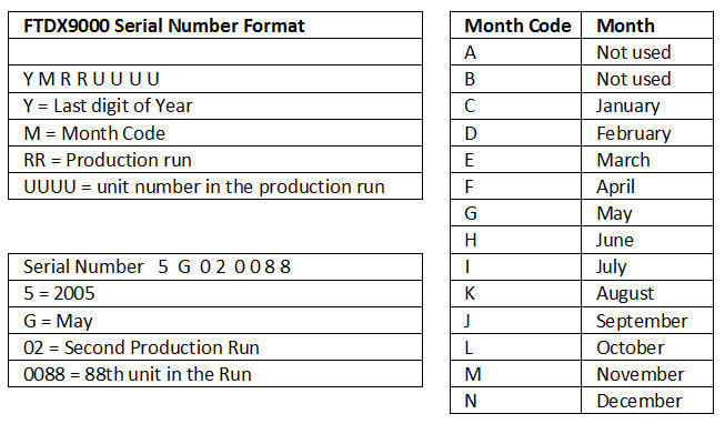
This is not new - it's just for reference. Use this conversion table to decode your serial number.
Lou / N2TU
A little history is in order here...if
you do a search in the FTDX9000 forum archives, you will see that some
developers had problems with their programs due to a mis-definition of the FT
command in the Operations Manual. In order to get around this, they ingeniously
developed programs to accommodate the FT command and the pre-PEP processing
slowness.
When the PEP 9000 was released with its updated CAT FT structure, there needed
to be some "tweaking" of the CAT, which has been successfully completed by
Japan. Additionally, the developers of the above mentioned software were made
aware of these changes and either have, or will be, modifying their rig files or
programs. The third possibility is that no change is required because their
program works with the existing CAT FT command.
Basically, Yaesu has now aligned the CAT FT commands for the 9000 PEP, 2000 and
950. I am unaware of any revisions to the pre PEP CT Command structure.
The purpose of my testing was to make sure the PEP would work some current logging and contest programs. Seeing I am only familiar with a few, DX4WIN, DX Labs and N1MM, those were the ones I chose for my "test". Test was in quotes because, I did not test all of the functions of these programs, only their ability to function with the PEP on simplex and split spots.
The FT Commands are exactly the same as the current FT-2000/D and the FT-950.
FT0 Command is the same as TX-VFO-A
button on the radio
FT1 Command is the same as TX-VFO-B button on the radio
(FT0 and FT1 are used to toggle between the TX-A and TX-B VFOs)
FT2 Command is for VFO A-TX (no toggle)
FT3 Command is for VFO B-TX (no toggle)
FT0 – FT3 should not affect any RX functions A or B VFO:
And more great news! The CAT Operations Manual for the FT9000PEP is going to be
revised next week to reflect the above, along with the FT2000 CAT manual (there
were some minor omissions).
Summary of enhancements
► The default contour setting (nulling) and peaking both work well. Offending signals are significantly suppressed by the nulling. The peaking ( i.e. + values) seem to be the preferred settings for CW.
► The new AutoPeaking mode was introduced with the PEP upgrade and works well. It provides a reduction in audio frequencies outside a narrow band and makes for easy listening for most CW signals.
► When adjusting the Contour control, the peaked frequency value (or notched value depending on the Menu Contour setting) is displayed at the bottom of the VFO A Screen in enabled by menu #22
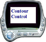 Short video showing the Contour control in operation with the
default NULL setting. The frequency is displayed and you
can hear the nulling effect.
Short video showing the Contour control in operation with the
default NULL setting. The frequency is displayed and you
can hear the nulling effect.
Contour Modes
The PEP version of the contour function introduces a new mode called AutoPeaking in addition to the normal mode. The two modes are distinctly
different in the way they interact with the contour control (aka contour
knob) and the menu settings. The mode options are Contour,
AutoPeaking, or both and your selection is enabled by
menu setting 88 (main rcvr) & 91 (sub rcvr).
For CW operators, selecting both APF and Contour is
suggested. More below.
Menu settings
Suggested contour menu settings for CW operation
Menu item #86 = +13 (provides peaking for weak signals)
Menu item #87 = 5 (fairly narrow peaking width)
Menu item #88 = APF & Contour (allows you to jump between both modes )
► Whether the Contour function operates in the peaking or nulling mode depends on the value set in menu item #86.
► The negative values have a very noticeable and increasing effect as you move towards the maximum of -40
► The positive values provide peaking as the value is increased to a maximum of +20.
► The contour control determines the frequency for the peaking or nulling and is displayed on the screen as you move the contour control.
► Menu item #22 determines whether the frequency is displayed (or not) for this control as well as other user selected controls.
► AutoPeaking mode only works for CW mode
► The contour control does not do anything when in AutoPeaking mode (except the frequency on the display changes which could lead you to think you are doing something)
► AutoPeaking overrides the normal action of the contour function and takes effect regardless of whether the normal action is peaking or nulling
► The amount of peaking is fixed (it's a special mode and it does not matter what you have set in menu 86)
► The function of the AutoPeaking mode is to significantly narrow the AUDIO bandwidth which reduces the level of nearby signals and noise. This reminds me of the audio DSP on the FT-920 which I really liked. Easy listening for most CW signals.
► Menu item #23 controls whether this mode is identified with a steady or blinking leg starting with V512.
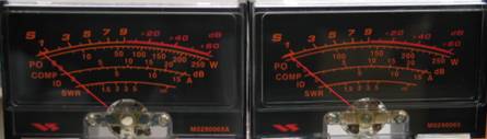
A small number of early production FTdx9000 power meters did not have the log power scale. As part of PEP they will be replaced with new ones that have the log scale on them to permit easier reading between 0 to 100 watts.
Please see the photo. The new meter is on the left....note the addition of 10 & 50 on the power line.
They are both RMS reading, not PEP.
FT DX 9000 Options and Accessories
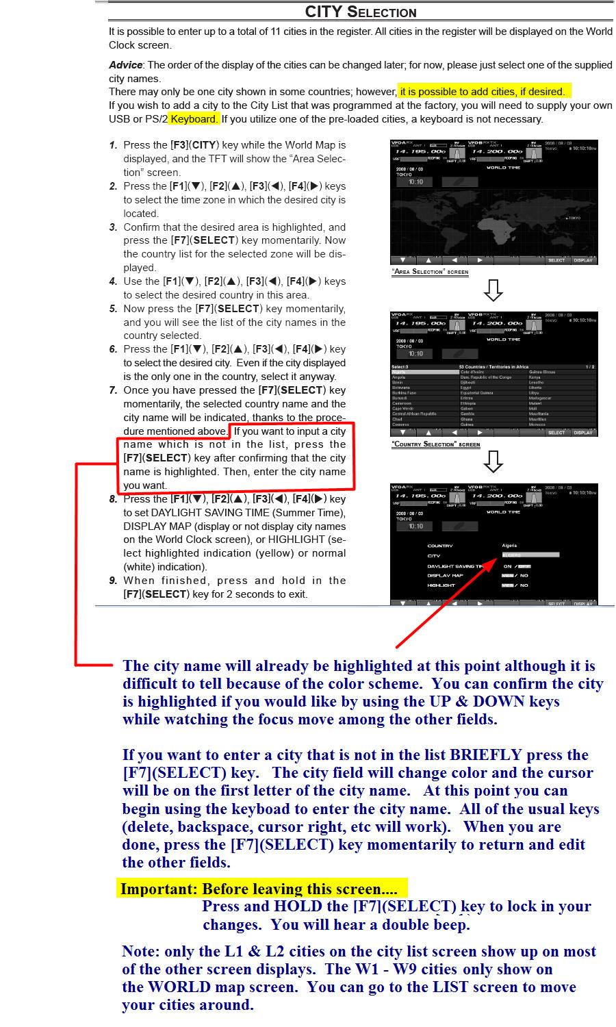
City Names & Custom City Names
The DMU/TFT option provides a number of graphical screens that you can configure. The default city name on the screens and world map is Tokyo. You can change the primary city and add a second city that will appear on most of the screens. You can add up to 9 more cities to the MAP screen. The documentation in the TFT manual has been improved but this process can be confusing. Below is a snapshot of page 9 from the TFT document with a few notes that may help.
If you want to enter city name that is not on the list of factory supplied names, you can do that. You need to connect a keyboard to the rig before you power it up so it will be ready when you get to step #7. Note prior to getting to the point of editing in your city name, in step #6, just pick one that is in the same country (and state if possible) and the time information will probably be correct with having to make additional edits.
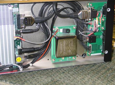
There have been a few cases of the oven failing. Here are the symptoms, how to verify the failure and replace the oven. If you need a new OCXO, it is very easy to replace. There are four screws and two connectors. No alignment is needed.
Symptom:
If the oven fails the frequency always goes low. Normally at 50 MHz the frequency should be within 10 Hz. You can check the oven by removing the right side cover. Then you will be able to see the OCXO, it is a 2 inch square metal can (Please see the below image for the OCXO location). Turn on the main power and after about 10 minutes touch the OCXO and it should feel warm, about 100 degrees. If the OCXO is not warm it must be replaced.
Replacement Procedure:
1. Remove the four screws
from the corners of the OCXO assembly board.
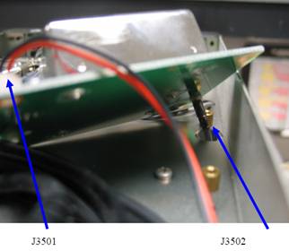
2. Remove the Red and
Black wire connector form J3501 on the top of the OCXO assembly board
3. Remove the coax cable
from J3502 on the bottom of the OCXO assembly board. Please see the image below.
4. Install the new OCXO
assembly by reversing the above procedure.
5. Do not align any
adjustments. The OCXO is factory aligned.
The new part number for the OCXO is REF-Unit board, Part CB3075001 as (H9500870) has been discontinued
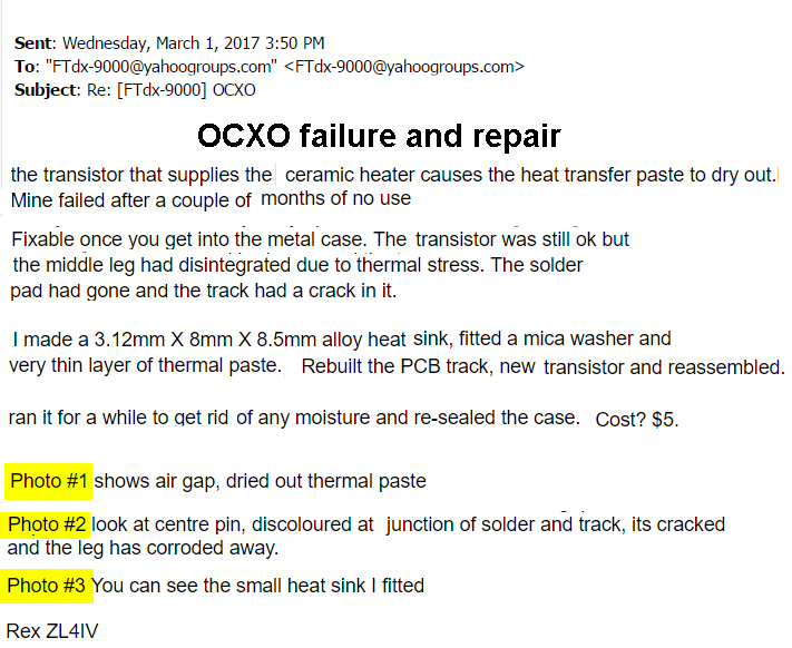
Rex / ZL4IV has found a failure in the OCXO that may be common and field repairable. Here is a summary of his notes and the steps to fix it.
NOTE: The following information is for educational purposes only. Yaesu does NOT recommend user installation of MTU units. Any use of the material for installation or any other purpose is at the users own risk.
Marty / KT4K provided the information and approved including the links to his installation instructions.
http://www.kt4k.com/UTUNEinstall.html
http://www.kt4k.com/UTUNEturnON.html
http://www.kt4k.com/UTUNEresultsl.html
Q - On the contest model, can I add the options like the uTuning units or DMU later if I don't get them initially?
A - Yes, the options can be added but it requires a trip back to the service center. They are not user installable per Yaesu. However, for the uTune units see the section above regarding self installation.
Q - Software version - After I finished my software update and used the 50, GEN, ENT salute to see the software version, all I see is 7.0000MHZ. What is going on?
A - Most likely one of the buttons was not depressed. After doing an update the default band on startup is 7.0000 MHZ and if you aren't holding all three buttons down this is what you will see.
Q - CW Speed display - How can I tell the current keyer speed setting?
A - The speed is dispayed momentarily when you adjust the SPEED control. You can also cause the speed to be displayed by pressing and holding the KEYER button. It will "double beep" and then display the current speed for as long as you hold the button. This does not toggle (or turn off) the keyer if you have it engaged. It does not toggle (or turn on) the keyer if you don't have it engaged. It merely displays the keyer speed setting.
Q - PEP Packing slip - What does "DO NOT USE PER MIKI MARUYA " on the packing slip mean? Is there a problem?
A - No problem, the phrase "DO NOT USE" is for internal use ONLY. It just means that those parts are for the PEP-9000 upgrades, and NOT to be used for the regular repairs.
Q - I'm looking for one of the older versions of the software for my 9000. Where can I find it?
A - All of the older versions of the software, manuals, etc are available on the Yaesu "Owners Corner." Click here for more from section on software updates.
Q - Are there any options to save, share, and restore the menu and memory settings (other than using the CF card)?
A - The very useful and FREE
FTdx9000 Memory & Menu Manager Software by HB9ZS for Storing, Backup, Managing,
Saving, Emailing, Restoring, is available at:
http://www.qslnet.de/member/hb9zs/ft9000/
Q - Is there any way to use the 2 receivers for diversity reception?
A - Yes, here are the steps. Set the 2 VFOs to the same frequency (press the A=B button). Set the menu item "tracking" (#40) to "freq." Now, when you tune VFO A, VFO B will follow. Tnx to Gaby/F5PSI for the info.
Joe / K2XX adds he has been using diversity reception with the 9000D on 80M with different antennas on each VFO. It works well, but if you accidentally hit the VFO B knob, you can lose synchronization. It can be restored easily with the A=B button, but you have to be aware that the antenna connected to VFO B will also be changed to the same as VFO A. The original antenna on VFO B has to be manually restored.
Q - Why does the CW auto mode not work sometimes?
A - Here is an explanation.
1. If you go into the SSB mode and BRK-IN was previously enabled in the CW mode, all is OK....the rig goes to CW as described in the Manual as soon as you tap the CW key. (Menu 53 must be set to ON.)
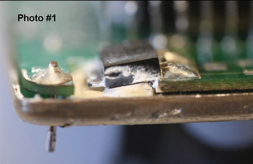
2. If you go into the SSB mode and BRK-IN was not previously enabled in the CW mode, CW Auto does not work...the rig does not go into CW as described in the Manual. Regardless of the setting of Menu 53.
So be aware, CW Auto Mode will only work if BK-IN was
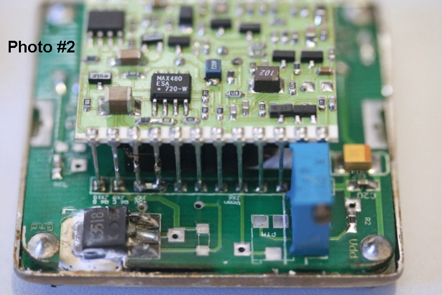
set in the CW mode
**before** switching to the SSB mode. Paul/W3GQ and Jon/W5AEM noticed this
anomaly with the CW Auto Mode operating procedure in the FT2K series.
Lou / N2TU worked with Yaesu and advises this also affects the 9000 & 950
series. Yaesu will update the manual with this information.
Q - Where can I find a copy of the Service Manual?
A - Google "FTDX9000 Service manual" and you will find several sources. The manual is about 40 mb and in the .pdf format. Here is one URL:
Q - Why are there 2 different versions of DMU software? (for example 4.20 and 5.10)
A - There are 2 different versions of the CPU used so that is why there are 2 different versions of the BIOS. Click for more information at the software history section for the DMU 420 update.
Q - Why is the fan running even when I first turn on the radio?
Info provided by Atsu/ JE1TRV. Per Yaesu Service in Tokyo.
There are two fan modes depending on when the radio was made. Also
different thesholds are required for some country's (I didn't ask country names
applicable)
[Power Supply Fan]
Mode 1: runs always.
Mode 2: runs only when temperature gets up a certain threshold.
[Main
Fan - TX Fan]
Mode 1: runs from 20deg C then speed increase by 20C step.
Mode 2: runs from 40deg C then speed increase by 20C step.
The modes are NOT configurable from the operator menus and don't appear to be available from the service menus either. Atsu had his rig set to mode 2 by returning it to the factory and reports good results and quiet operation now.
Note: The questions and answers above are based on emails I've received and feedback I've gotten from various sources. They are not official replies from Yaesu so please take my "answers" for what they are worth. If you have any Q&As you think might be helpful to others, please send me a note and I'll post them.